Finless Heat Exchanger
Finless Heat Exchanger
Fin-and-Tube Heat Exchanger is the most widely used heat exchanger in the refrigeration and air conditioning industry, and copper tube and aluminum fins are the main components of finned tube heat exchanger. It is generally believed that the main thermal resistance of finned tube heat exchangers is on the air side, so how to design more efficient fins has always been the top priority of finned tube heat exchanger research. The industry has developed reinforced surfaces such as corrugated sheets, bridges, window openings, and various fins with vortex generators.
Require Quotation? Send E-mail to : commercial@bestfintube.com
One of the development directions of copper pipes is to reduce the diameter, and 5mm pipes have been applied. However, as the tube diameter becomes smaller and smaller, the dominant role of the fins in heat transfer is weakened, even without fins, resulting in a Micro Bare Tube Heat Exchanger, or Finless Heat Exchanger.
A study from the University of Maryland [1] shows that when the tube diameter is less than 1 mm, the finless heat exchanger can achieve the same compactness as the fined heat exchanger, and the smaller the tube diameter, the gap shrinks rapidly. As shown in Figure 1, the abscissa is the diameter of the tube, and the ordinate is the heat exchange area per unit volume (commonly used to measure the compactness of the heat exchanger). For conventional tube diameters, finned heat exchangers are more than 20 times more compact than finless heat exchangers. When the tube diameter is 1 mm, the finned heat exchanger is only about twice as compact as the finless heat exchanger. If the tube diameter is further reduced, the compactness of the finless heat exchanger will be close to that of the finned heat exchanger. This shows that when the pipe diameter is small enough, the heat exchange area of the finless heat exchanger is not much different from the heat exchange area of the finned type in the same volume, and the role of the fin as an "extended surface" no longer exists.
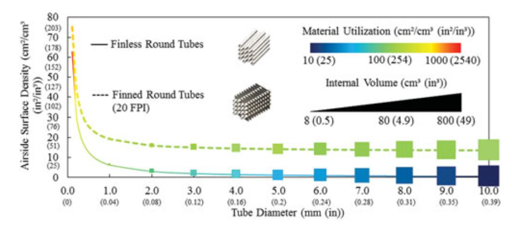
Fig.1. Variation of heat exchanger compactness with pipe diameter (Source: Ref. [1])
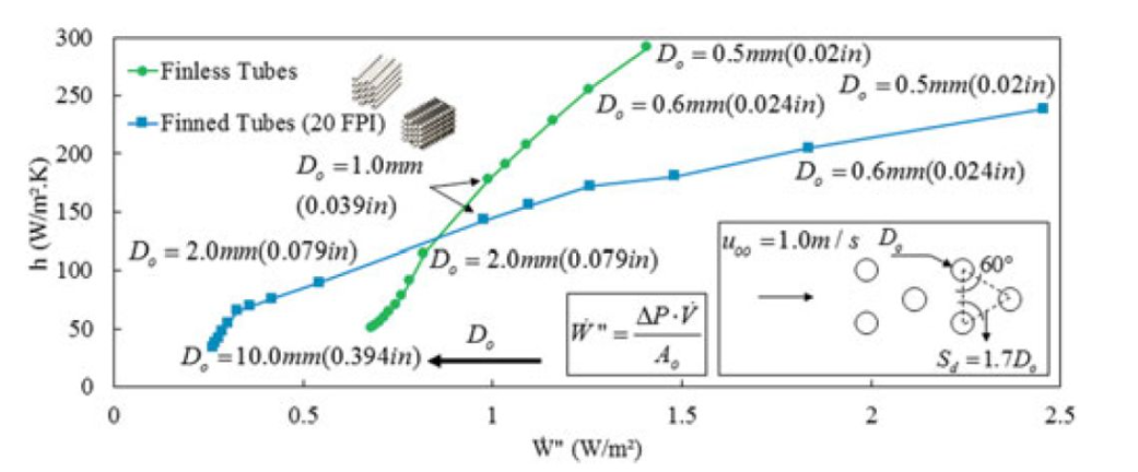
Figure 2 shows a comparison of the finned and unfin heat transfer coefficients, where the abscissa is the cost of heat transfer - the power consumption spread over the unit heat exchange area. It can be seen that there is an intersection between the two curves, between 1-2mm in diameter. On the right side of this intersection, the heat transfer coefficient of the wingless type is higher than that of the finned type when the heat transfer cost is the same.
Fig.2 Comparison of heat transfer coefficients between finned and finless types (Source: Ref. [1])
As you can imagine, another advantage of this type of microfluorescent tube heat exchanger is that it has a significantly lower refrigerant charge. Researchers from Zhejiang University [2] used a similar low-light tube heat exchanger for the R290 household split air conditioner, successfully reducing the charge to about 250g, thus meeting the EU standard. The microfluorescent tube heat exchanger they designed is structurally similar to a parallel-flow heat exchanger, as shown in Figure 3. The heat exchanger tube is a stainless steel tube with an outer diameter of 0.58mm. The actual product is shown in Figure 4.
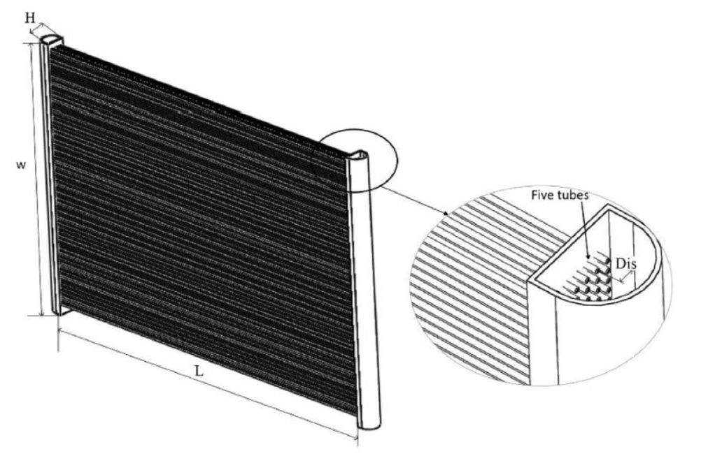
Fig.3. Schematic diagram of low-light tube heat exchanger (source: Ref. [2])
Fig.4. Condenser (left) and evaporator (right) using low-light tube heat exchanger (Source: Ref. [2])
Researchers at the University of Maryland have also developed a bifurcated bare tube heat exchanger based on the fractal geometry theory [3], a schematic diagram of which is shown in Figure 5. The numerical simulation results show that when the outer pipe diameter is 0.8mm, the air side heat transfer coefficient of the bifurcated light tube heat exchanger is 15% higher and the pressure drop is reduced by 4-12% compared with the straight tube microfluorescent tube heat exchanger. They also used 3D printing to make a physical object (see Figure 6) for testing. Unfortunately, it was reported that only the air-side pressure drop was tested due to a leak.
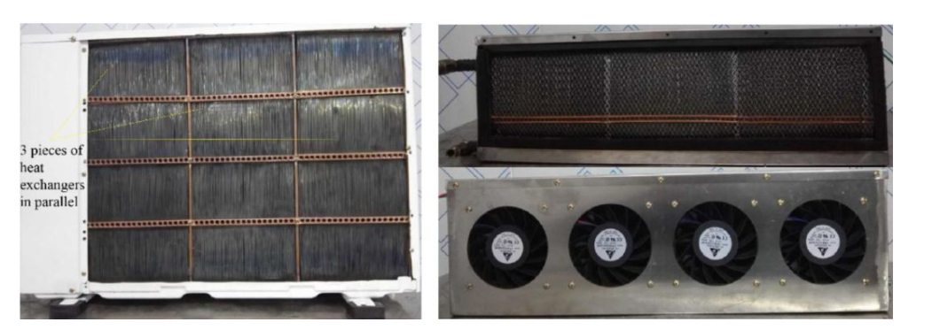
Fig.5. Schematic diagram of bifurcated fluorescent tube heat exchanger (Source: Ref. [3])
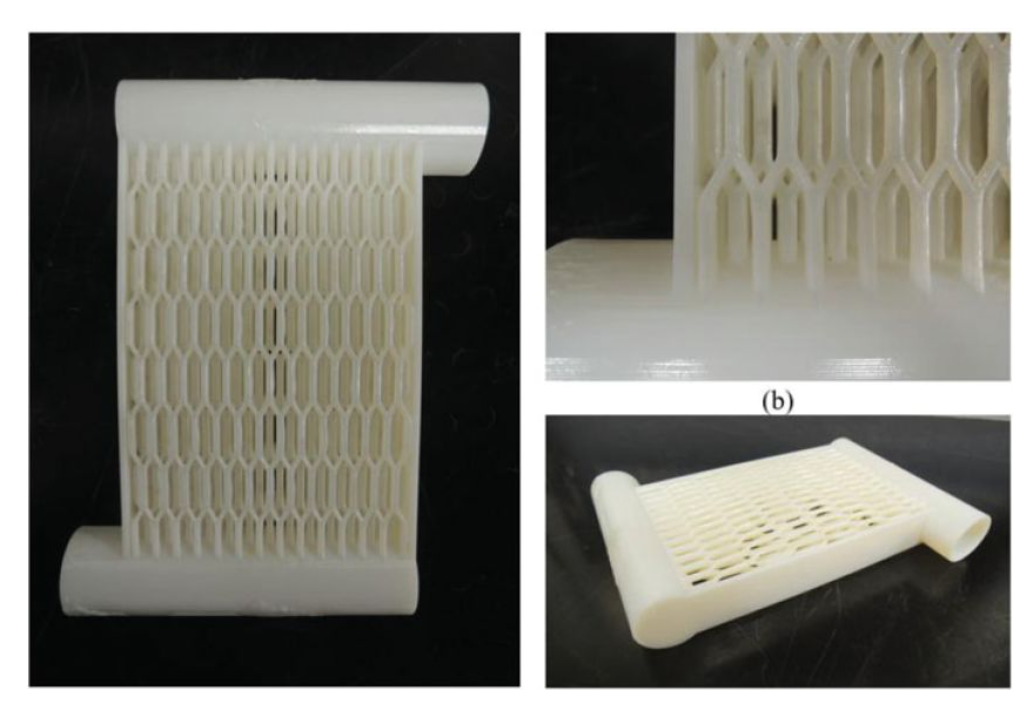
Fig.6. 3D printing sample of bifurcated fluorescent tube heat exchanger (Source: Ref. [3])
It is worth pointing out that despite the above-mentioned advantages of microfluorescent tube heat exchangers, the disadvantages are also obvious. For example: (1) the number of tubes in the low-light tube heat exchanger is very large, and when used as an evaporator, the two-phase refrigerant is easily distributed unevenly; (2) How to process microfluorescent tubes using traditional methods; (3) When the tube length is long, how to ensure that the microfluorescent tube does not bend and deform. In general, the microfluorescent tube heat exchanger is still in the early stage of research, and the advantages and disadvantages depend on the further discovery of practitioners.
References
[1] Bacellar, D., V. Aute, Z. Huang and R. Radermacher (2017). "Design optimization and validation of high-performance heat exchangers using approximation assisted optimization and additive manufacturing." Science and Technology for the Built Environment 23(6): 896-911.
[2] Zhou, W. and Z. Gan (2019). "A potential approach for reducing the R290 charge in air conditioners and heat pumps." International Journal of Refrigeration 101: 47-55.
[3] Huang, Z., J. Ling, Y. Hwang, V. Aute and R. Radermacher (2017). "Design and numerical parametric study of a compact air-cooled heat exchanger." Science and Technology for the Built Environment 23(6): 970-982.


